How to Splice Small Gauge Wires
- Feb 28, 2026
Learn how to make a reliable butt splice connection on small gauge wire, including selecting the correct splice size, stripping, crimping, and heat shrinking.
Table of Contents
Affiliate Disclosure: This website may contain affiliate links. The creator of this website may earn a commission from qualifying purchases made through these links at no additional cost to you.
How to Splice Small Gauge Wires
Butt splice connectors are one of the most practical tools in a van builder's electrical kit. They allow you to join two wires end-to-end quickly and reliably. Whether you're extending a wire run off of your Maxxair fan, making a repair, or connecting two sections of a circuit, knowing how to make a clean butt splice connection is a skill you'll use throughout your build.
By the end of this guide, you'll know how to select the correct butt splice for your wire gauge, how to properly strip your wire, how to crimp the connector, and how to seal the connection with a heat gun.
Step 1: Select the Right Butt Splice for Your Wire
Butt splice connectors are color-coded by the wire gauge range they are designed to handle. Before reaching for a connector, identify the gauge of the wire you are working with. Using the wrong size connector — one that is too large or too small for your wire — will result in a weak crimp that can fail under vibration or load, both of which are constant realities in a moving vehicle.

The three most common color codes you'll encounter are:
- Red — 22–16 AWG
- Blue — 16–14 AWG
- Yellow — 12–10 AWG
Always verify the AWG range printed on the connector packaging before purchasing. In a van build, smaller gauge wires such as those used in lighting circuits, sensor wiring, and other low-current applications will most commonly call for a red connector — but always confirm the gauge of the wire you are working with before selecting.
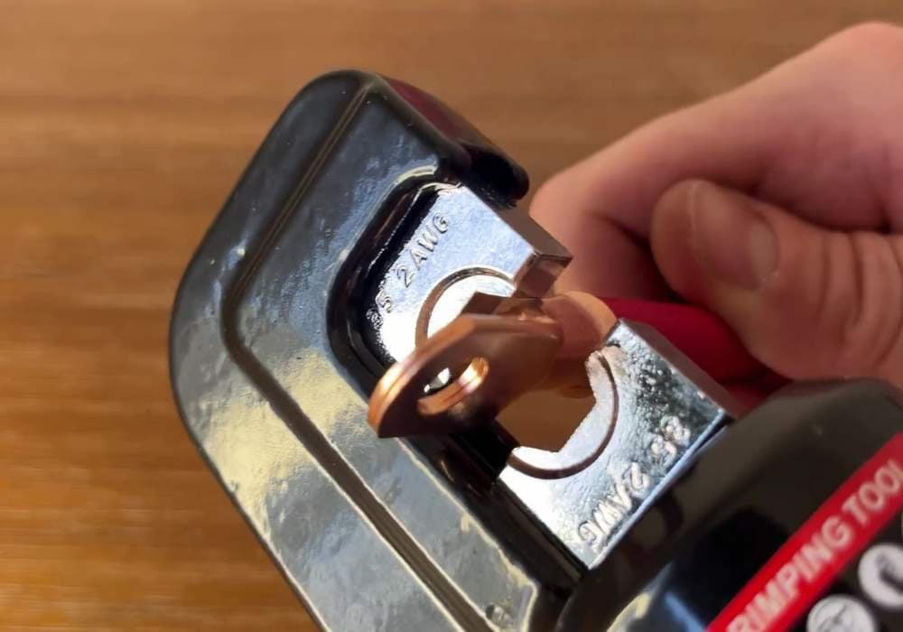
Step 2: Identify the Correct Crimping Channel
Your crimping tool will have multiple crimping channels, each corresponding to a specific wire and connector size range. Locate the channel that matches the AWG range of the connector you have selected. The channels are typically labeled with their AWG ranges and will correspond to the same color-coding system as the connectors themselves.
It is important to match the channel to the connector size rather than the wire gauge alone. The connector itself determines which channel to use. Using a channel that is too large for your connector will result in an under-crimped connection that is both electrically unreliable and physically insecure.
Step 3: Strip the Wire
Before inserting the wire into the butt splice, you need to strip away a short length of the insulation to expose the bare copper strands. On a standard wire stripper, locate the stripping groove that matches your wire's gauge. Insert the wire into that groove, close the jaws firmly, and pull the wire straight through to remove the insulation cleanly.
Aim to expose approximately 3/8 to 1/2 inch of bare wire. Too little, and the wire won't seat fully inside the connector's metal barrel. Too much, and you risk having bare copper exposed beyond the connector after crimping — a potential short circuit hazard. Using the correct stripping groove for your wire gauge ensures the insulation is cut cleanly without nicking the copper strands underneath, which would weaken the wire at that point.
Step 4: Insert and Crimp the First End
With the wire stripped, insert the exposed copper strands fully into one end of the butt splice connector. The wire should seat into the metal barrel inside the connector. You should not be able to see bare copper extending beyond the clear heat shrink tubing on the connector.
Place the connector into the matching channel of your crimping tool, positioning it so the metal barrel of the connector sits in the jaw. Squeeze the crimping tool firmly until the handles close and the crimp is complete. Most quality crimping tools will ratchet and not release until a full, proper crimp has been applied. After crimping, give the wire a firm tug to confirm the connection is secure. If the wire pulls free, the crimp did not engage properly — discard the connector and start with a new one.
Step 5: Insert and Crimp the Second End
Repeat the same process on the opposite end of the butt splice connector. Strip approximately 3/8 to 1/2 inch of insulation from the second wire, insert it fully into the open end of the connector, and crimp using the same matching channel on your crimping tool. Again, tug firmly to confirm the connection is solid before moving on.
At this point, both wires should be mechanically joined through the butt splice connector. The connection is electrically functional, but it is not yet sealed against moisture or vibration. That is what the next step addresses.
Step 6: Seal the Connection with a Heat Gun
Heat shrink butt splice connectors have a layer of heat-activated adhesive-lined tubing built around them. When heat is applied, this tubing shrinks tightly around the connection, creating a moisture-resistant, insulated seal. This is what separates a professional-grade connection from a basic crimp — and in a van build environment, where wires are exposed to vibration, condensation, and temperature swings, this seal matters.
Use a heat gun set to a moderate temperature and apply heat evenly across the length of the connector, moving the heat gun slowly back and forth. You will see the tubing shrink and conform tightly around the wire on both ends. The adhesive inside will also flow and seal the edges. Once the tubing has fully contracted and the adhesive is visible at both ends, the connection is complete. Avoid holding the heat gun in one spot for too long, as excessive heat can damage the wire insulation.
Always use heat shrink butt splice connectors in your van build. The sealed connection provides protection against moisture and corrosion that a plain crimp cannot offer.